
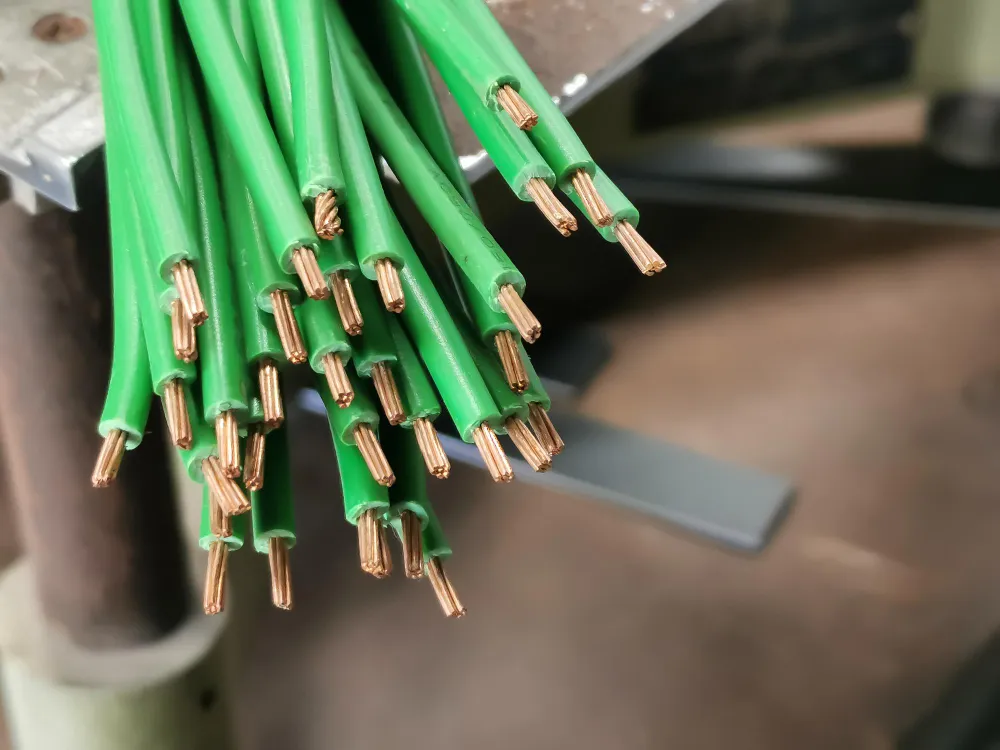
6 AWG ground wire is often specified where electrical equipment needs a substantial copper conductor for its protective grounding system. The wire may look like an ordinary building conductor with green insulation, but it serves a different purpose than carrying electricity to an appliance. When a fault energizes a metal enclosure, a correctly designed grounding path helps fault current return to the source so protective equipment can disconnect the circuit.
The distinction matters when planning a workshop, commercial building or high-power electrical installation. A thick green wire cannot compensate for loose connections, an incorrectly selected breaker or a missing bond between metal parts. The conductor must have the right material, size, insulation rating and termination for the complete system.
What 6 AWG ground wire actually does
An equipment-grounding conductor connects exposed conductive parts, such as metal equipment frames and enclosures, to theinstallation’ss protective grounding network. Under ordinary operating conditions, it is not intended to carry the current used by lights, motors or other loads. That current travels through the circuit’s supply and return conductors.
If a damaged live conductor touches an equipment enclosure, the metal can become energized. A continuous, low-impedance fault path provides an alternative to a person’s body and allows enough current to flow for an appropriate fuse or breaker to open. The federal explanation of equipment grounding identifies that protective function and the danger of a broken path.
It is misleading to picture the green wire as simply carrying dangerous electricity into the soil. In a typical grounded AC installation, the effective fault path returns toward the electrical source through bonded conductive parts. Earth plays a different role in the overall grounding system and is not a dependable substitute for a metallic fault-current path.
Why the green insulation identifies a safety conductor
Electrical installations use conductor identification so installers and maintenance workers can distinguish different functions. In common U.S. building wiring, green or green-with-yellow markings identify an equipment-grounding conductor. A bare conductor can also serve that purpose where the wiring method allows it.
The neutral is a different component. It is an intentionally grounded circuit conductor that can carry current during normal operation. An equipment-grounding conductor should not be repurposed as a neutral or an energized line simply because its copper cross-section is large enough to carry current.
Colors do not establish whether a circuit has been wired correctly. Renovations, field modifications and damaged labels can create dangerous assumptions. A qualified electrician must verify the actual connections and installation design rather than use insulation color as the only evidence.
What 6 AWG means for a stranded copper conductor
American Wire Gauge is a system for sizing conductors. In this system, smaller gauge numbers represent larger conductor cross-sections. A nominal 6 AWG copper conductor has an area of about 13.3 square millimeters, although the overall insulated wire is wider because of its protective layers.
Stranded construction uses several smaller copper wires grouped into one conductor. It can be easier to route through bends than a single solid conductor of comparable area, particularly in larger sizes. The number and arrangement of strands depend on the cable construction and applicable specifications.
That flexibility does not mean it is suitable for repeated movement. Ordinary building wire installed in conduit should not be treated as a continuous-flex cable for a moving machine. The conductor, connectors and mechanical protection must match whether the installation is fixed or subject to vibration and motion.
THHN and THWN-2: why the insulation markings differ
THHN and THWN-2 identify different temperature and environmental conditions that a wire’s insulation system supports. In common dual-rated building conductors, a thermoplastic insulating layer and protective nylon covering withstand the installation environment. Confirm the exact construction in the applicable product markings and technical specifications.
The THHN designation indicates high-heat-rated, thermoplastic, nylon-covered wire for appropriate dry locations. A THWN-2 marking supports use in wet and dry locations at a rated conductor temperature of up to 90 degrees Celsius, subject to the product’s listing and installation conditions. A dual marking means the conductor has been assessed for both sets of conditions.
Those temperature values do not authorize running every circuit at the ampacity shown in the hottest column of a wire table. Terminal ratings, conductor grouping, ambient temperature and the rules for the chosen wiring method may impose tighter limits. A protective grounding conductor also has a different sizing purpose from a normal current-carrying conductor.
What a 600-volt wire rating does and does not say
A 600-volt marking describes an insulation voltage rating for the intended applications. It does not mean a green equipment-grounding conductor normally operates at 600 volts, or that it should be connected to a live terminal. In ordinary service, the protective conductor is intended to remain near the potential of bonded equipment.
Insulation rating is only one part of selecting wire. The installation must still satisfy rules for conductor identification, mechanical protection, overcurrent devices, enclosure fittings,s and environmental exposure. A wire that is suitable inside an approved raceway may not be permitted to lie unprotected across the ground or be used as a portable extension cord.
Product listings can also have more than one environmental designation. A wet-location marking does not automatically approve every kind of direct burial, immersion or outdoor exposure. The actual product marking and applicable wiring method govern what is permitted.
How ground faults cause breakers and fuses to operate
Consider a hypothetical metal-cased machine with damaged insulation inside. If an energized conductor touches its housing, the enclosure may rise to a dangerous voltage. A properly bonded equipment-grounding conductor gives the fault an effective path toward the source, allowing high fault current to flow where the circuit design anticipates it.
That current can operate the overcurrent protective device, disconnecting the faulted circuit. Whether it clears promptly depends on the available fault current, the total path impedance and the characteristics of the breaker or fuse. A thin, damaged or poorly connected path may not carry enough current for a rapid protective response.
Official electrical wiring and protection requirements distinguish equipment grounding from ordinary circuit conductors. The core engineering requirement is a permanent, effective path, not merely a green wire somewhere inside the enclosure.
Why grounding and bonding are connected but different
Grounding describes electrical connections within the broader reference and protective system. Bonding connects conductive parts so they don’t remain at dangerously different potentials and so the fault-current path remains continuous. A metal junction box and its attached conduit can require suitable bonding even when a separate green wire is present.
Paint, corrosion, loose fittings and incompatible metal connections can interrupt an intended bond. A conduit fitting that appears mechanically secure may still fail to provide an effective electrical connection if it is installed incorrectly. This is one reason enclosure and raceway details matter as much as conductor gauge.
Some approved metal raceway systems can themselves form part of the equipment-grounding path. Others require a separate conductor. The correct approach depends on the wiring method and its approved fittings; adding a conductor does not make poor metalwork or an unapproved connection acceptable.
Why 6 AWG is not the correct ground size for every circuit
A common mistake is to choose an equipment-grounding conductor solely by matching the live conductors or by buying the thickest available wire. For many installations, minimum wire-type equipment-grounding conductor sizes are based on the rating of the circuit’s overcurrent protective device, with additional rules for specific circumstances.
That means a 6 AWG green wire may be larger than required for one circuit and unsuitable as the sole grounding solution for another. If circuit conductors are enlarged, special sizing considerations may apply. A grounding electrode conductor, which serves another purpose, follows a different set of selection rules.
There is no safe universal answer to what breaker a 6 AWG ground wire can support. Engineers and electricians must consult the locally adopted electrical code, the equipment instructions and the actual circuit design. An insulation label and a product-page specification cannot settle that decision.
Where a green stranded conductor is typically used
Commercial switchboards, equipment feeders, motor installations and large building circuits can require insulated equipment-grounding conductors. A green stranded copper conductor may be routed alongside the associated circuit conductors in an approved conduit or cable assembly, depending on the electrical design.
Fixed industrial machinery presents a familiar example. Electrical faults in a motor or control enclosure can make accessible metal surfaces hazardous. The protection system depends on a coordinated arrangement of grounding, bonding, overcurrent protection, and safe equipment construction, not a single wire size.
High-power residential loads can also make grounding design important, but equipment-specific instructions and adopted local codes control the installation. For readers researching a wider range of components, the hardware coverage section provides related technology reporting; no dedicated grounding article was identified for a closer internal link.
Wet locations, conduit and moisture create extra constraints
Conductors routed outside or through underground raceways may encounter moisture even if their ends are in a dry building. Electrical design should therefore use a wire insulation designation permitted for the actual location. A dual THHN/THWN-2 marking is useful because the wet-location rating addresses an exposure that dry-only insulation cannot.
Moisture protection does not eliminate the need for correct terminations. Water can enter damaged enclosures, corrosion can affect contacts, and cable pulls can damage insulation. The conductor may also need protection against sharp edges and excessive pulling forces during installation.
Long conductor runs add practical issues of routing and continuity. Cut-to-length stock can reduce unnecessary offcuts, but the delivered length must still allow suitable termination without tension. Any permitted splice must use a connection method and enclosure appropriate to the actual conductor and location.
How copper terminations can become a weak point
A stranded wire depends on a connector designed and rated for its material, size,e and strand class. If a terminal is not suitable for the conductor, its contact area may be unreliable. Over- or under-tightening can also damage the connection or leave it loose.
Heating at a poor connection is especially concerning during an electrical fault, when current can rise far above normal load levels. A grounding path should be effective throughout the circuit, not just where a continuity tester touches an exposed end. Installation instructions for the selected connectors remain essential.
Copper provides useful electrical conductivity, but it does not make every connection immune to corrosion or damage. Mechanical stress, vibration and exposure to incompatible materials can change contact quality over time. Inspection and testing are part of the protection system, not optional finishing touches.
Grounding conductors and ground-fault interrupters solve different problems.
A fuse or conventional circuit breaker responds to particular current and fault conditions. A ground-fault circuit interrupter detects an imbalance between intended current paths. It can disconnect a circuit when a normal breaker may not trip quickly enough to protect a person.
The two protective measures are not interchangeable. An interrupter does not make a damaged equipment-grounding connection acceptable, and a grounding conductor does not replace all requirements for ground-fault protection. The required safeguards depend on the circuit, occupancy and application.
The official grounding continuity guidance also shows why testing matters: a protective conductor can be physically present while its connection is broken. Tests and inspections must be selected and performed by people qualified for the equipment and work involved.
What engineers verify before accepting a grounding installation
Before energizing a circuit, a qualified person must confirm that the chosen wiring method, conductor identification, and protective device fit the design. The review includes the grounding path, approved terminals and whether metal enclosures and fittings are bonded as required. A green jacket on the correct gauge of copper is not enough to pass that assessment.
Commissioning checks can identify missing connections, damaged insulation or unexpected continuity problems. The appropriate procedures depend on the system and must be conducted safely with suitable instruments and isolation methods. Related testing of electrical distribution hardware also examines protective grounding, overload response and insulation performance. Untrained people should not open energized panels or attempt fault-current testing.
Good documentation identifies the installed conductors, circuit protection, approved wiring route and relevant inspection results. Future maintenance may change equipment or add loads, so a clear record helps technicians avoid assumptions about a circuit that was installed years earlier.
When a larger ground wire helps and when it does not
Using a larger conductor can be appropriate when the electrical design requires it, including certain runs with special sizing considerations. But conductor size alone does not determine fault protection. Connection quality, path geometry, protective-device behavior and the rest of the bonding network also affect the result.
Oversizing without a design reason may raise costs and make conductors harder to route or terminate. Undersizing can leave an installation unable to meet its protection requirements. You can’t evaluate either choice from a retail listing without knowing the circuit configuration and adopted standards.
6 AWG ground wire is best understood as one possible component of a properly engineered protective system. Green identification, suitable copper construction and the correct environmental rating help define its role. The actual safety benefit comes from making the entire fault-current path continuous, properly sized and capable of operating the intended protection when something fails.