
Articulated robots are often considered when factory workers must repeat the same difficult movement hundreds of times per shift. A machine shop may need someone to load a cutting machine all day. A welding line may depend on a torch following the same seam with consistent speed and angle. A six-axis robot arm can take over controlled movement, letting people focus on setup, inspection, and exceptions.
That does not mean every repetitive job should be automated. Parts can arrive in different positions, grippers can lose their hold, and an arm reaching a machine may still collide with its door. The engineering question is not simply whether a robot can move fast. It is whether the complete process can run safely, produce acceptable parts and recover when conditions change.
What makes a six-axis industrial robot different?
An articulated robot is a mechanical manipulator made of rigid links connected by rotating joints. Many industrial models have six controlled axes: three largely position the arm and three help orient the wrist and attached tool. The arrangement gives a controller considerable freedom to approach an object, though not every orientation is possible at every point in the working area.
Other robot designs solve different problems. A gantry moves along linear rails; a parallel robot often uses linked arms for fast movement over a defined area. A six-axis articulated arm is useful when a tool must rotate and approach a part from changing directions. It is not automatically the fastest or simplest choice for moving every object.
The arm is only one part of an industrial installation. It needs a controller, motors, feedback sensors, electrical power and an end effector such as a gripper, welding torch or dispensing head. Surrounding machinery must also communicate when it is ready for the next step.
How six axes position and turn a tool
The first joint generally rotates the arm about its base. Shoulder and elbow joints move the larger links, shifting the wrist through the workspace. The remaining axes can change tool orientation, allowing a nozzle or gripper to point toward a surface while the arm maintains a suitable approach.
Each joint has operating limits. The controller calculates how a set of joint angles places the tool in three-dimensional space, a calculation known as forward kinematics. Inverse kinematics works in the other direction: given a desired tool position and orientation, it searches for joint configurations that can achieve them. Several valid solutions may exist, each producing a different arm posture. One may keep the elbow clear of a fixture, while another brings it dangerously close. At some configurations, called singularities, the robot can lose useful freedom of motion or require very fast joint movement to maintain the commanded tool path. Programming has to account for these conditions.
Why payload and reach can rule out a robot
Arobot’ss reach describes how far its working reference can extend under defined conditions. Payload describes the load it is rated to handle, subject to operating conditions and manufacturer limits. These specifications help narrow a selection, but they do not prove that a given tool and workpiece can be moved along a particular path.
The gripper, welding equipment, hoses, and carried object all contribute to the load. The distance between their combined center of mass and the wrist changes the torque required at the joints. An object that weighs less than the robot’s nominal payload can still create an unsuitable load when held far from the tool mounting point.
Factory layouts add another constraint. A robot may have enough nominal reach to touch a machine opening but no collision-free route through it. Engineers examine the full working envelope, mounting height, tool geometry, cable routing and the space needed for maintenance before approving an application.
The accuracy problem: repeatable does not mean correct
Manufacturers often describe robot precision using repeatability: how closely the tool returns to the same taught location over repeated movements. Accuracy asks a different question. Did the tool reach the intended physical location in the first place?
A robot can repeat a slightly misplaced position with excellent consistency. That may be acceptable for a task taught directly against a fixed fixture, but it becomes a problem when the program relies on a digital design or when a part changes location. Federal research on robot accuracy and repeatability explains why both measures matter for manufacturing quality.
Calibration establishes the relationship between the robot’s joints, its base, the end effector and the workpiece. Temperature, wear, mounting changes and tooling replacement can change those relationships. Precision work therefore requires verification at the tool tip, not just confidence in a published specification.
How the controller plans safe and useful motion
A robot program can request movement between joint positions or specify a tool path through the workspace. These are different commands. Moving the joints together can produce a curved tool trajectory, while a straight tool path may demand more complex coordination among the axes.
Controllers also manage acceleration, deceleration and allowable speed. Fast motion saves time only when the arm, tool, and carried object can tolerate the forces. A tall part may sway, a gripping surface may slip, and a welding process may require a steadier pace than the robot’s maximum motion permits.
Collision checking must consider the whole arm, the tool and the workpiece, not only the endpoint. A route that clears a machine while it is empty might strike an open door or a full parts bin. This is why robot programs are normally tested in controlled conditions before automatic operation.
Factory problems articulated robots can solve
Welding is a common use. A six-axis arm can keep a torch at a defined angle and travel along a programmed seam while the welding equipment controls the process. Spot welding requires the robot to position a heavier tool and manage its approach to the workpiece. Both applications depend on fixtures, part consistency and process settings.
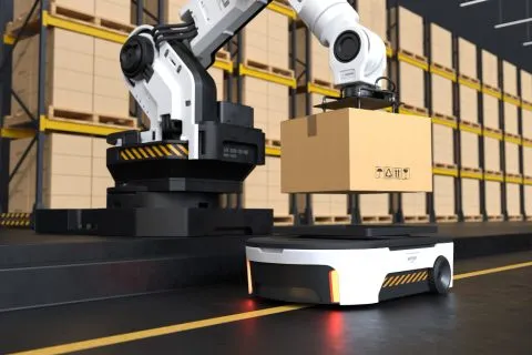
Machine tending addresses a different bottleneck: production equipment may wait for an operator to load the next blank or remove a finished part. A robot can repeat that transfer while exchanging signals with doors, chucks and clamps. It must confirm the machine is stopped and the fixture is ready. If machining takes several minutes, making the arm move a second faster may have little effect on total output.
Painting, dispensing and finishing demand control over tool orientation and movement speed. Material handling may prioritize payload, reach and gripping reliability instead. For production lines using interchangeable equipment, the related guide to modular robot cells explains how the arm fits into a broader system of conveyors, fixtures and safeguards.
How offline programming reduces costly trial and error
Engineers can build a virtual representation of a robot cell before installing all the hardware. A model of the arm, tooling, machines, and safety boundaries lets them explore reach, potential collisions, and cycle times. The software may also run a virtual version of the robot controller to check how programs behave.
This process is often called offline programming or virtual commissioning. It can reduce the need to interrupt a running production line for every program change. Still, a simulated workstation is only as accurate as its geometry, calibration and assumptions about the real process.
Loose parts, changing friction, damaged fixtures and unexpected operator behavior may not appear in the virtual model. The physical cell still needs commissioning and validation. Tools that simplify program creation do not eliminate these duties, as discussed in the explanation of no-code robot programming.
Can robot vision handle parts that move or vary?
A traditionally programmed robot expects a workpiece at known coordinates. Cameras and depth sensors can estimate the location and orientation of parts that arrive with some variation. The controller can then adjust a permitted pickup or processing path instead of relying solely on a fixed position.
AI-assisted vision may help distinguish objects, identify defects or propose grasp points. It does not remove the need for calibration or a defined response when recognition is uncertain. Reflective metal, poor lighting, and overlapping objects can still confuse a camera, and the resulting motion must remain within validated limits.
There is growing interest in systems that use demonstrations and simulated experiences to propose robot actions. For factory use, those approaches must be judged by measured performance on real materials and unfamiliar conditions. A robot that recognizes a part is not automatically able to grip it securely or finish an assembly.
Safety depends on the completed application.
Industrial arms can move heavy tools through a large working envelope. Unexpected starts, dropped workpieces, and crushing points create risks during normal production, especially during teaching, cleaning, or maintenance. Safety cannot be established simply by fitting a newer controller or calling a system collaborative.
The U.S. industrial robot safety guidance describes task-specific risk assessments, guarding, monitored protective functions and safe work procedures. International standards updated in 2025 distinguish requirements for the robot itself from requirements for integrating complete robot applications and cells.
An appropriate installation may use interlocked fences, presence sensors, speed limits and defined recovery procedures. The chosen safeguards depend on the task and the equipment around the arm. An AI-generated motion or changed tool path must never bypass the independent protective functions.
Why a faster arm may not increase production output
Cycle time is only one measure. Process speed may limit a welding cell more than a machine-tending robot can, leaving much of its shift waiting for machining to finish. Measure throughput over complete production runs, including part supply, quality checks, and interruptions.
The measures that matter are good parts per shift, time lost to jams and changeovers, maintenance work, scrap and operator interventions. A cell that moves quickly but drops one part in every short run can cost more than a slower, stable process. Throughput claims should come from the complete production cycle, not the robot arm’s maximum speed.
The purchase price of the arm rarely represents the full project cost. Fixtures, guarding, programming, grippers, training, and integration can add up. Any claim that a robot pays for itself within a particular period needs a workload-specific calculation, not a general marketing percentage.
When an articulated robot is the wrong solution
Flexibility is not the same as general-purpose intelligence. A conventional six-axis robot executes defined movements and responses within an engineered system. It can handle changing conditions only to the extent supported by its sensors, software, tools and validated operating rules.
Some tasks remain difficult because parts deform, arrive randomly or require unusually fine contact control. Others need a long horizontal travel distance that a rail-mounted or gantry system could provide more simply. When every part follows the same short route, a specialized mechanism may be more economical than a more versatile arm.
Articulated robots are likely to become more adaptable as perception, simulation and control improve. Their practical value, however, will continue to depend on matching the arm to the work: the right payload and reach, a reliable process, verified safety and performance measured across real production shifts.