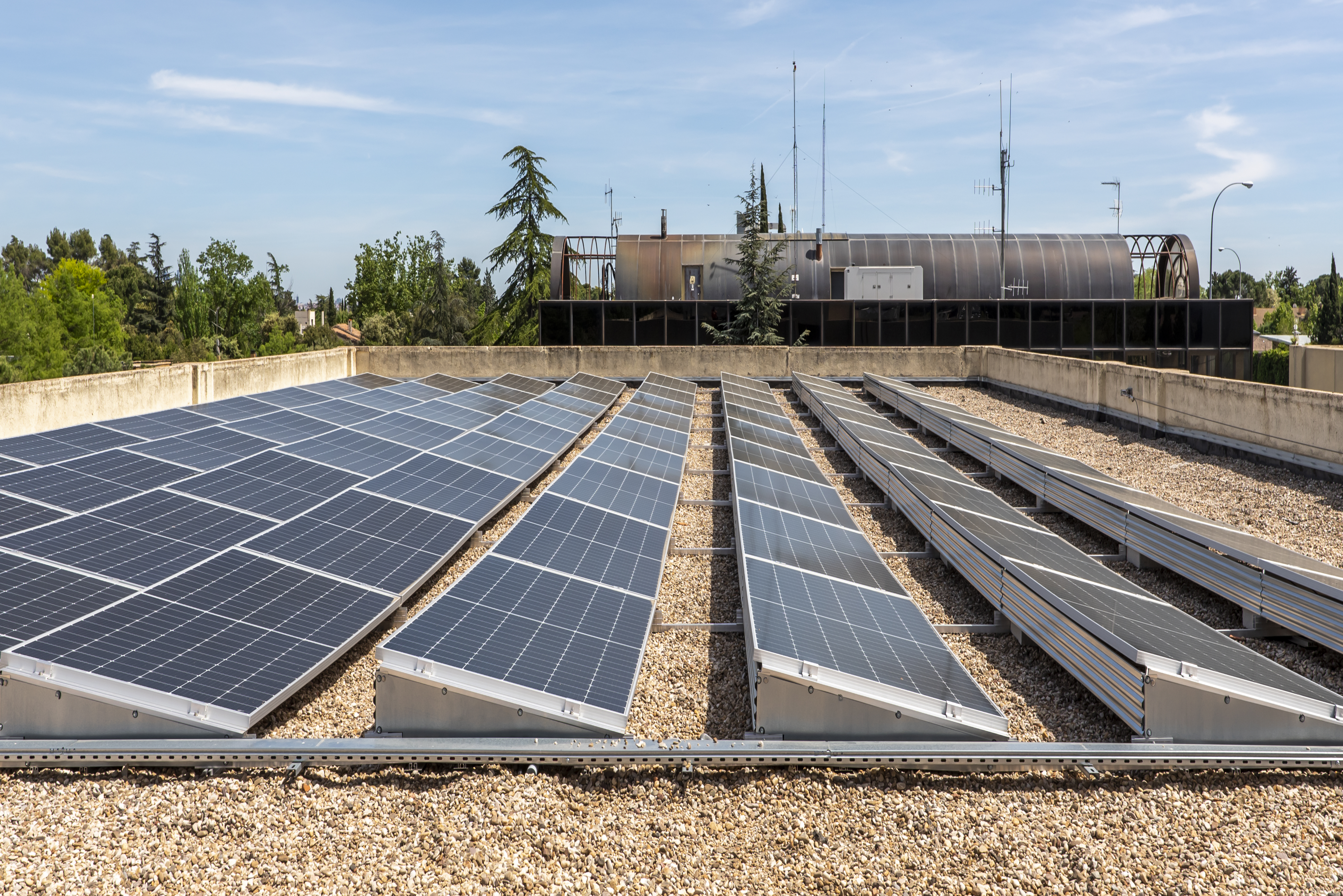
A solar array can be perfectly positioned to capture sunlight and still be unsuitable for the roof beneath it. On a flat commercial building, the critical question is often not how much electricity the panels might produce. It is how the support system will stay in place during strong winds without adding more weight than the structure can safely carry.
Ballasted solar racking holds photovoltaic modules in position using engineered weight rather than relying entirely on fasteners through the roof. The arrangement can reduce penetrations in a waterproof membrane, but it creates a difficult balance among wind uplift, sliding resistance, concentrated loads, and drainage. Choosing the lightest possible rack isn’t necessarily safer, and adding more ballast isn’t necessarily an acceptable solution.
What ballast actually does on a flat roof
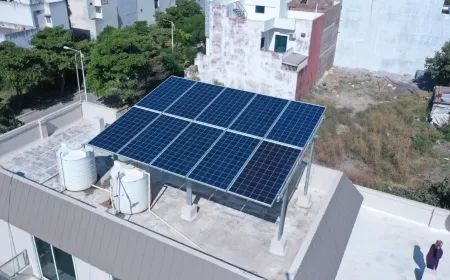
A ballasted mounting system typically places low-tilt module supports on protective pads or trays, with blocks or other specified weights positioned according to an engineered layout. The weight helps resist uplift and movement. Modules, clamps and supporting frames must also transfer forces reliably into that support arrangement.
That does not make the installation equivalent to placing heavy objects on the roof. The load imposed by one group of blocks may differ sharply from the average weight calculated across the entire array. A structural review must consider how forces reach the roof deck and supporting members, not simply divide the system’s total mass by the available roof area.
Some designs combine ballast with mechanical connections to the building. Those hybrid systems use attachments where additional restraint is required. The design choice depends on wind exposure, roof condition, building capacity, and applicable engineering requirements, rather than the assumption that one mounting method is always preferable.
Why wind uplift is not the same as a downward load
Wind moving over a building can create pressure differences above and below tilted modules. As air flows around roof corners, parapets, and rooftop equipment, it can create turbulence that lifts, twists, or slides an array. The forces change with wind direction, module tilt, roof height and the arrangement of neighboring panels.
Roof corners and edges deserve particular attention because local pressure patterns can differ from those in central roof areas. A layout based on one uniform weight per panel can miss those variations. The engineering problem is to establish the forces each zone must resist and design a stable path to the supporting building.
The U.S. Department ofEnergy’ss severe-weather guidance warns that turbulent flow around parapets and rooftop structures can make fully ballasted arrays vulnerable. Its recommendations include strategically placed mechanical attachments where needed and racking that can resist movement under changing wind loads. This is a design warning, not a blanket statement that all ballasted installations are unsafe.
The structural load has to travel somewhere.
A photovoltaic module does not carry wind forces directly into the building. Pressure reaches the module frame, passes through clamps or bolts into rails and supports, and finally acts through pads, anchors or ballast on the roof. A weak link anywhere along that path can undermine the strength of the remaining components.
Mechanical failure can begin at a small joint: a loose clamp may let a module shift, increasing the load on adjacent connections. Repeated vibration can also reduce the effectiveness of some fasteners. The Department of Energy identifies critical joints, lateral bracing and resistance to twisting as important elements of PV installation and commissioning.
A design review therefore needs the module’s permitted attachment locations, the support system’s tested or engineered capacities and a plan for installing hardware to the specified condition. A component’s strength in isolation does not prove that the entire assembled array will resist an extreme event.
Roof load capacity limits available ballast
Before selecting ballast, an engineer must establish what the existing building can support. The assessment includes the weight of modules and racking, added ballast, relevant snow and maintenance loads, and how those loads are distributed into the roof structure. The condition of an older roof may differ from its original design assumptions.
Ballast can be especially demanding at corners and edges where greater restraint may be needed. Adding weight at a support point can create a concentrated load even when the average load seems modest. The roof deck, insulation and underlying structure may each respond differently to that pressure.
A roof with little remaining reserve capacity may require a lighter array configuration, additional structural reinforcement, a different mounting layout or engineered mechanical attachments. The key takeaway is site-specific: no universal ballast weight or roof-area allowance can determine an individual project’s safety.
Protecting the waterproof membrane and drainage paths
Fewer roof penetrations can reduce the number of locations that require waterproofing details. They do not eliminate the possibility of roof damage. A support pad can press into roofing materials, a shifting rail can abrade the membrane, and a heavy array may restrict access to drains or make inspection more difficult.
Assess contact materials for compatibility with the roof assembly. Protective layers may distribute load and reduce abrasion, but they must stay properly positioned throughout the installation’s life. Maintenance crews also need a way to examine areas concealed by the racking.
Water is both a structural and a roofing issue. If a roof deflects or drains slowly, ponded water can add load and worsen the condition that allowed it to accumulate. Designers should account for drainage routes, existing low spots, access to outlets and the combined effects of ballast and water rather than treating leak prevention as a final installation detail.
Panel tilt changes both energy capture and wind exposure
A steeper panel angle can improve solar collection under some conditions, but it also changes how moving air acts on the array. Low-profile rows can reduce certain aerodynamic loads while making dirt accumulation, drainage behavior and maintenance clearance more important. Consequently, sunlight alone does not determine the best tilt.
Spacing and orientation also matter. Rows placed close together may create different pressure patterns from isolated panels. Nearby parapets, vents, and taller equipment further complicate airflow. An engineering model should reflect the actual roof geometry rather than assume open, unobstructed conditions.
A government-laboratory study of rooftop photovoltaic slat modules examined how an alternative module geometry let air pass through the array and reduced wind loading in tested configurations. The research illustrates a design trade-off: changing the shape and airflow path may reduce the required ballast, but experimental results from one configuration cannot automatically transfer to another roof.
When mechanical anchoring becomes part of the answer
Where ballast alone cannot meet the structural and wind requirements within the roof’s load capacity, mechanical restraint may be needed. Attachments can transfer forces into structural members instead of relying only on weight and friction. That can reduce some ballast requirements, although it introduces penetrations and detailing that must be compatible with the roof system.
Anchors must connect to a suitable structural element, not merely to the outer roofing layer. The penetration needs an engineered weatherproof detail and a maintenance plan. Its location can also affect roofing warranties, future replacement work and the ability to remove the array without extensive repairs.
Hybrid mounting is therefore a trade-off, not a shortcut. Fewer blocks may ease dead-load constraints, but anchors require careful structural and waterproofing design. A safe decision depends on the combined performance of the roof and mounting system under the site’s governing loads.
Electrical bonding and cable routing remain structural neighbors
The racking holds electrical equipment outdoors for years. Conductive module frames and metallic support components may need electrical bonding as part of the installation’s required fault-protection system. The permitted connection method depends on the equipment’s evaluated assembly and applicable electrical rules; assume that ordinary physical contact between metal pieces does not provide a reliable bond.
Wiring also needs a defined route. Cables left against sharp edges or exposed to repeated movement can damage their insulation. Supports, clips and protective pathways should account for sunlight, moisture, thermal movement and future roof maintenance. Wind that loosens hardware can also displace wiring if restraint is inadequate.
These details link mechanical design to electrical safety. A mounting layout should leave room for required access, conductor support, a nd service operations, rather than forcing installers to improvise after the rails and modules are already in place.
Commissioning should test the installed system, not just the drawings
Installation quality cannot be demonstrated by a computer layout alone. The installed array needs checks against approved drawings, hardware specifications, fastening procedures, ballast placement and any engineered attachment schedule. Review unexpected roof conditions before crews adjust the design in the field.
For critical joints, installers need the specified tools and documented torque procedures. Inspectors should check clamp engagement, rail connections, bracing and cable protection. Structural review and electrical testing are complementary; passing one does not establish that the other is satisfactory.
The first inspection also establishes a useful baseline. Photographs, as-built layouts, equipment records, and known roof conditions help maintenance teams spot later movement, missing protection pads, or signs of water damage. A roof installation that cannot be inspected is harder to keep reliable.
What maintenance must look for after severe weather
Even a correctly engineered system can develop problems after long exposure to vibration, temperature changes and storms. Inspectors should look for displaced ballast, loose or corroded connections, changed module alignment, abrasion, trapped debris and blocked drains. Roof repairs may also disturb a mounting system that previously operated normally.
The Department of Energy’s PV maintenance guidance calls for preventive inspections, storm preparation and post-event checks, including fastener and electrical assessments where appropriate. The scope of any inspection must match site safety conditions; damaged electrical equipment should not simply be restarted to see whether it works.
Owners should retain roof and solar documentation together. Replacing the roofing membrane can require partial or full removal of the array, with consequences for labor, storage, warranty administration, and recommissioning. Evaluate the array’s service life and the roof’s remaining service life as one project.
The design decision goes beyond ballast versus bolts
Structural stability, watertightness, service access and electricity production can pull a roof design in different directions. A dense array may capture more power from limited space but complicate access. Heavier ballast may avoid some penetrations while worsening structural or drainage constraints. More anchors may solve an uplift problem but increase roofing work.
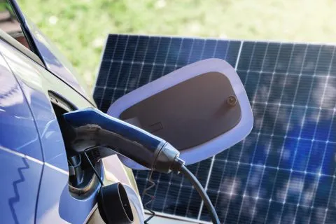
That distinction matters when comparing rooftop generation options. A separate analysis of high-efficiency solar cells explains how electrical output can improve at the cell level; those gains cannot substitute for a safe mounting structure. Another report on using rooftop solar power for EV charging addresses energy management after electricity is generated, not the roof’s ability to support the array.
For a flat-roof project, the useful comparison is between fully engineered alternatives that satisfy the same building and weather requirements. Ballasted solar racking can be appropriate where load capacity and wind conditions permit it. Where they do not, additional anchors, changes to array geometry or structural work may be necessary. The final determination belongs to the qualified design and permitting process for the actual building.