Why a solar cell can lose electricity before it reaches a wire
A solar cell does not convert every useful photon into electrical power. Some light is reflected, and some energy becomes heat. Even when sunlight creates mobile electrons and holes inside silicon, those charges can disappear through recombination before the circuit collects them. TOPCon solar cells are designed to reduce one important part of that loss: what happens at the semiconductor’s electrical contacts.
The name stands for tunnel oxide passivated contact. It describes a contact structure, not an entire rooftop energy system. The engineering goal is to collect useful charge carriers while reducing unwanted recombination at the silicon surface. Better cell performance can help a module generate more electricity from a limited area, but the outcome still depends on manufacturing quality and operating conditions.
How TOPCon solar cells use silicon and selective contacts
The basic photovoltaic process starts when light generates charge carriers. Most industrial TOPCon designs use an n-type crystalline silicon wafer. A doped emitter on one side forms the junction that separates charge carriers when light is absorbed. The other side includes a very thin silicon oxide layer and a heavily doped polycrystalline silicon layer beneath the metal contact. The arrangement is often described as a passivating or carrier-selective contact.
The oxide reduces the number of electrically active defects where the wafer meets the contact structure. Those defects can provide pathways for electrons and holes to recombine, costing the cell power. The adjacent doped silicon helps move the intended carrier toward the external circuit. The contact must therefore solve two competing problems: block loss-producing recombination without making it too difficult for current to flow.
The details vary by process and cell layout. The familiar rear-contact arrangement should not be mistaken for a rule that every module has the same layers, metallization pattern or performance.
Why the tunnel oxide must be extraordinarily thin
An ordinary insulating oxide would obstruct electrical current. In a TOPCon contact, the oxide is thin enough for charge transport through quantum-mechanical tunneling and related contact transport pathways, depending on its microstructure. A national laboratory presentation describes a representative oxide thickness of about 1.5 nanometers. That is a reference structure, not a universal specification for every production cell.
Thickness and uniformity matter. A poorly formed interface can increase recombination, while an unsuitable contact structure can raise electrical resistance. The result may be a lower voltage, reduced fill factor or both. Manufacturers must control the oxide growth, deposition conditions and subsequent thermal processing closely enough to maintain the intended balance.
The physics is subtle, but the practical test is straightforward: the contact should preserve charge separation and allow current to leave the cell with minimal additional losses.
Where the efficiency improvement comes from
Solar conversion efficiency measures the share of incident solar energy converted into useful electrical output under defined test conditions. The U.S. Department of Energy identifies recombination, reflection and temperature as important sources of loss. Passivating contacts address recombination; they do not eliminate optical losses, heating or resistance elsewhere in the device.
Engineers examine open-circuit voltage, short-circuit current, fill factor and maximum power. A contact that reduces recombination may improve voltage. A contact with excessive resistance can undermine the gain by lowering fill factor. These measurements must be considered together, because a higher voltage alone does not prove a better finished module.
Cell efficiency also differs from module efficiency. Glass, encapsulation, cell spacing, ribbons and other module materials affect how much sunlight becomes useful output at the panel terminals. Installed energy yield adds further variables, including angle, shade, dirt, inverter behavior and the weather.
What changes on a photovoltaic manufacturing line
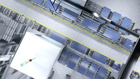
The process begins with prepared silicon wafers, surface texturing,g and carefully controlled doping to form the junction. The passivating contact requires additional cleaning, oxide formation and deposition of doped polycrystalline silicon. Metallization and firing create conductive pathways while preserving the properties of the layers underneath.
High-volume production adds practical constraints that laboratory cells do not always show. Small variations in surface contamination, furnace temperature, coating uniformity or metal paste can affect thousands of cells. Inspection may use current-voltage testing, photoluminescence or electroluminescence imaging to identify electrical defects and damaged regions before module assembly.
A transition from an older cell process is not necessarily a complete factory replacement. Still, compatibility does not eliminate the cost of new tools, process qualification, waste handling, and yield losses during commissioning. The economic question is how much additional usable output survives those manufacturing trade-offs.
How cells become modules that can operate outdoors
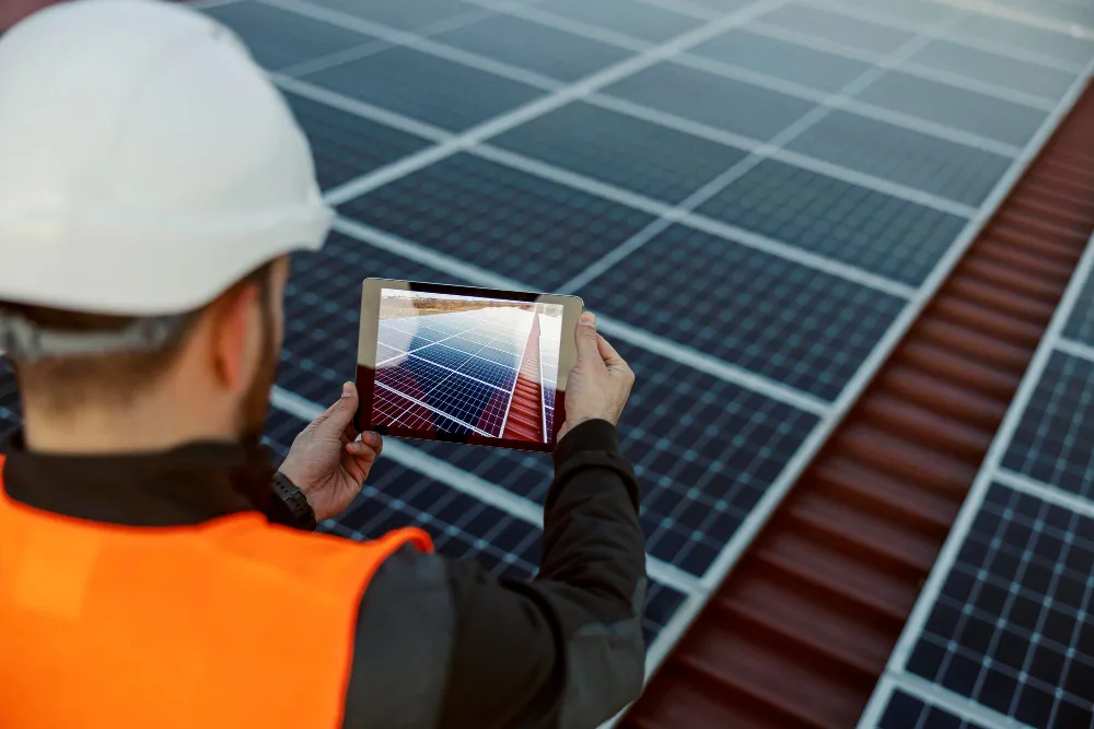
Individual cells are interconnected into strings and laminated with protective materials between front and rear layers. Contacts and ribbons carry current, while encapsulants and edge seals help shield sensitive parts from moisture and mechanical damage. A frame, junction box, and bypass diodes may complete the module assembly, depending on its design.
Some modules use bifacial cells and transparent backs to collect reflected light on the rear side. The benefit depends on mounting height, surface reflectivity, obstruction and installation geometry. Other module choices, including half-cut cells and interconnection layout, can affect resistance and shading behavior without changing the underlying passivating-contact principle.
A roof-mounted cell is only one part of the energy path. The related solar EV charging explainer examines how rooftop modules’ electricity is measured and used downstream.
Why moisture can damage otherwise efficient cells
Electrical performance can deteriorate after years outdoors even when a module initially passes factory testing. Water vapor can enter through imperfect edge seals, backsheets or other material interfaces. Combined with elevated temperature and contaminants, moisture can accelerate corrosion at metallization and interconnection points.
The symptoms are not limited to a visible rust mark. Increased series resistance can reduce the current and power delivered under load. Interface damage can increase recombination, while damaged connections may create local heating. Laboratory damp-heat tests expose modules to controlled temperature and humidity to reveal vulnerabilities sooner than ordinary outdoor observation would.
Those tests are useful screening tools, not exact clocks for future field failures. Chemistry, encapsulant formulation, cell processing, and local climate all affect how accelerated results translate to real-world operation.
What ultraviolet exposure and passivation degradation reveal
Ultraviolet radiation can change the behavior of some passivation layers and interfaces. In affected cells, the loss may appear as altered voltage or other electrical characteristics rather than an immediately visible crack. A national laboratory research presentation on TOPCon contact reliability examines degradation and recovery behavior in silicon oxide and polycrystalline silicon contact structures.
Not every observed laboratory mechanism is equally important outdoors. Temperature, exposure dose, test sequence and cell construction can change both the severity of an effect and whether partial recovery occurs. A manufacturer’s claim of excellent long-term performance should therefore be evaluated against the actual bill of materials and relevant independent test results.
There is also a distinction between passivation degradation and conventional heat-related output loss. A hot panel ordinarily produces less power while operating at elevated temperature. Permanent or slowly recovering material changes require separate evidence.
How reliability testing connects laboratory results to field performance
A reliability program combines initial electrical measurements with stress exposures and follow-up diagnostics. Thermal cycling can reveal fatigue at solder joints or interconnects. Damp heat challenges moisture barriers and contacts. Ultraviolet exposure examines light-sensitive materials, while potential-induced degradation testing probes electrical stress under specified conditions.
A single pass/fail label hides the details engineers need. They should examine the test method, sample size, degradation distribution, preconditioning and whether results come from cells or complete modules. Two panels with the same nominal wattage can behave differently after equivalent stress if their materials and assembly processes differ.
The federal research description for TOPCon degradation illustrates why scientists study structural changes and electronic behavior together. A test that measures output loss without identifying the failure mechanism provides limited guidance for correcting the process.
Installation, safety and energy-yield limits
High cell efficiency does not override ordinary electrical safety. Modules generate direct-current voltage in sunlight, and strings can present hazardous voltage even when the inverter is disconnected from the utility. Mounting, conductor sizing, protective equipment, rapid-shutdown requirements where applicable and local electrical rules need professional evaluation for the specific installation.
A design assessment also needs the module’s actual voltage and current ratings, temperature coefficients, mechanical load limits and allowed system voltage. None of those values can be inferred from the word TOPCon alone. The finished panel’s certified ratings and installation instructions determine permissible electrical configurations.
Long-term energy estimates should use climate data and measured system losses rather than a cell-efficiency headline. Shade, inverter clipping, soiling and downtime may outweigh modest differences between cell architectures in particular locations.
Costs, maintenance and the life-cycle trade-off
A technically better contact structure may add little value if manufacturing rejects rise or field failures require early module replacement. Evaluating costs means tracking wafer processing, deposition equipment, energy and chemical use, encapsulation choices, quality inspection and warranty exposure. Lower production cost per watt and lower cost per lifetime kilowatt-hour are related but not identical objectives.
Owners typically cannot repair the microscopic oxide contact inside a laminated panel. Maintenance focuses on installation condition, wiring, connectors, visual damage and electrical performance trends. When a module shows a persistent fault, diagnosis may require electrical testing and imaging by trained personnel rather than opening the laminate.
End-of-life recovery adds another limitation. Glass, aluminum and some metals can be recovered through appropriate recycling processes, but separating encapsulated materials and handling retired modules remain logistical and economic challenges. Improving efficiency should not come at the expense of durability or disposal.
Where passivated-contact research goes next
Research continues on contact uniformity, lower-resistance metallization, degradation-resistant interfaces, and manufacturing sequences that preserve passivation after thermal processing. Better accelerated tests could help distinguish field-relevant defects from changes caused mainly by unusual laboratory conditions.
Advanced silicon cells may also serve as the lower junction in tandem devices that absorb different parts of the solar spectrum. Such stacks introduce further challenges in optical matching, electrical connection, stability and manufacturing yield. Laboratory performance does not guarantee that a tandem module will deliver the same output outdoors over decades.
TOPCon solar cells show why efficiency and reliability must be developed together. A well-designed contact can reduce electrical losses inside the silicon. Still, its value depends on whether the entire module continues to deliver useful power after years of sunlight, heat and weather.