Silfab Solar back-contact technology changes the way electricity leaves a photovoltaic cell and travels through a finished panel. Instead of relying on the familiar network of metal ribbons crossing the illuminated face, certain modules use rear electrical contacts and a patterned conductive backsheet. The design seeks to collect current while leaving more of the cell’s front surface exposed to sunlight.
That rearrangement is only part of the engineering problem. Contacts must remain accurately aligned, electrically isolated from the wrong polarity and connected through decades of heating, cooling and mechanical movement. The result depends on manufacturing quality and module packaging, not merely the absence of visible front-side wiring.
What Silfab Solar back-contact technology changes
A conventional crystalline-silicon solar cell converts light into moving electrical charges. A metal contact network then collects those charges. In many familiar designs, narrow fingers and thicker busbars sit on the illuminated surface, while other contacts connect at the rear. The front conductors occupy some of the area that would otherwise absorb light.
A back-contact arrangement relocates collection points to the rear of the cell. This can reduce optical shading from front metallization and give designers different ways to distribute current. The Department of Energy’s photovoltaic-cell explanation describes the underlying conversion of sunlight into electrical current. Moving the contacts does not change that basic semiconductor process.
Back-contact is a family of designs, not proof that every cell uses the same junction layout. Some place both electrical polarities in alternating rear regions; other approaches route contacts through the cell or alter module interconnection. The detailed semiconductor architecture must be established for each cell, not inferred from the module’s appearance.
How a conductive backsheet connects neighboring cells
In a conventional panel, cell-to-cell connections often use metallic ribbons soldered between front and rear contact points. An integrated conductive backsheet provides a different route. Patterned conductive paths sit within a laminated rear assembly and connect to appropriately positioned contacts on the back of each cell. Insulating regions are necessary to prevent unintended connections between adjacent paths.
Silfab describes an integrated module design that combines back-contact cells, an insulating layer, and a copper conductive backsheet. It calls this approach a monolithic conductive backsheet. The company also describes a rear-contact pattern intended to distribute current across its cells. These are descriptions of its product architecture, not independent proof of a particular efficiency or lifespan advantage.
Because the backsheet participates in the electrical circuit, it must do more than protect the module from the weather. Engineers need to consider conductor thickness, path resistance, bonding materials, contact alignment, insulation integrity, and how electrical paths cross from one cell to the next.
Why reducing front-side metal can improve power output
Light striking an opaque metal grid is not absorbed by the silicon beneath it. Moving conductors away from the light-facing surface can reduce this optical loss. It can also permit a relatively unobstructed appearance, but appearance alone does not measure electrical performance.
The gain is constrained by losses elsewhere. Current can still be lost through resistance in the rear contacts, metal traces and interconnections. Poorly passivated semiconductor surfaces can also increase recombination before a charge reaches the circuit. The Department of Energy’s efficiency guide distinguishes reflection, recombination, temperature and electrical measurement factors.
A useful comparison therefore requires measured current-voltage curves, maximum power and module efficiency under the same test conditions. Fewer visible front conductors should not be translated into a guaranteed percentage improvement over another panel.
Why rear-contact alignment is difficult
Electrical connection points must land on the intended conductive features, with enough tolerance for cell placement and material movement during lamination. An offset contact can increase resistance or leave an incomplete connection. A conductive feature that bridges neighboring polarities may create a shunt and reduce power.
Fine patterns also change inspection requirements. Engineers may examine electrical continuity, insulation resistance, contact geometry and cell-to-module losses during production. Image-based inspection can help locate broken cells or poor interconnections, while electrical testing determines whether those defects affect usable output.
Silfab announced the acquisition of self-aligned back-contact patents in 2025. That announcement describes a technology-development direction; it does not establish that every existing module incorporates the patented process. A production claim would need a specific cell or module revision and supporting documentation.
What the backsheet and insulation layers must withstand
The rear assembly experiences heat, sunlight-related aging, humidity and repeated expansion and contraction. Copper and polymer layers do not necessarily move at the same rate as silicon or glass. Repeated stress can challenge interfaces and electrically conductive bonds, particularly where materials have different thermal expansion behavior.
Insulation must preserve separation between live conductors and other module components. A useful backsheet design also needs a reliable moisture barrier and adhesion throughout the laminate. These characteristics are related but distinct: a material that conducts heat well does not automatically provide better electrical isolation or long-term moisture resistance.
Silfab says its copper layer helps spread heat from the cells. That physical proposition is plausible in principle, but the temperature benefit for a finished module depends on the entire thermal stack and real operating conditions. Independent, like-for-like thermal measurements would be needed to quantify any advantage.
How modules are assembled and tested
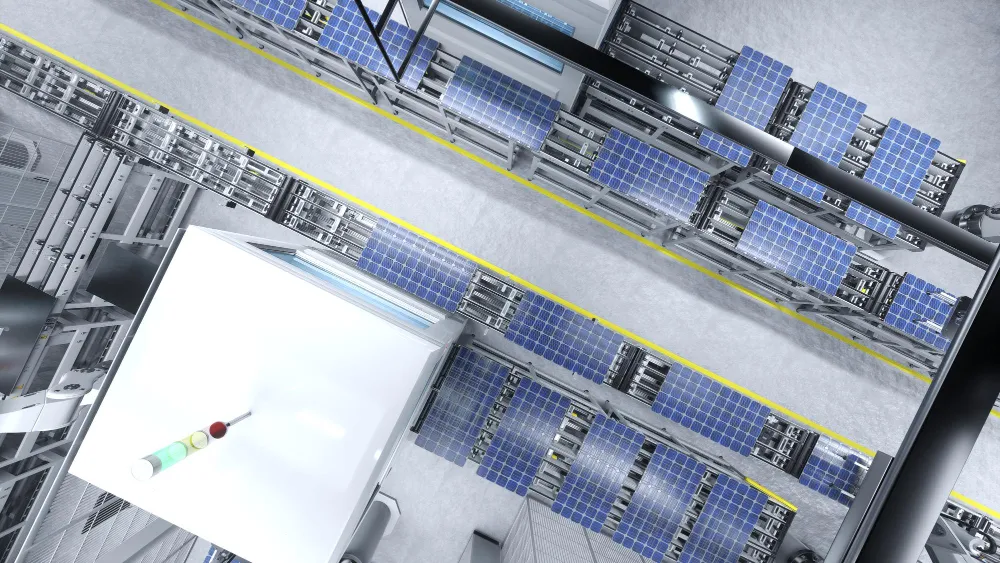
Module production begins with fabricated and electrically characterized cells. In an integrated rear-contact design, a precisely patterned backsheet and contact interface must be positioned to match the cells. The stack is combined with encapsulation layers and front glass, then laminated to protect the circuit from the outdoor environment.
The Department of Energy’s manufacturing overview describes conventional tabbing, stringing and lamination. Conductive-backsheet construction changes the interconnection stage, but it still requires electrical testing, controlled encapsulation, edge protection, and a safe output connection.
Inspection should separate cosmetic defects from electrical defects. A dark, visually uniform module can still have a high-resistance contact, a damaged cell, or an internal isolation problem. Production quality data, sample qualification tests and field performance records answer different questions and should not be treated as interchangeable evidence.
What thermal cycling, moisture and cracks can reveal
A rear-contact design may avoid some of the mechanical constraints of front-to-back ribbons, but it creates its own contact interfaces. Thermal cycling can stress the conductive bonds and laminated layers. Moisture ingress can encourage corrosion or undermine adhesion; cracks in the silicon can interrupt current collection even when the glass appears intact.
Accelerated tests help reveal weaknesses under controlled stress. They cannot by themselves predict an exact service life for every roof and climate. The Department of Energy’s reliability program explains why understanding degradation mechanisms and consistent testing matter for decades-long operation.
Failure diagnosis can combine electroluminescence images, infrared inspection, insulation checks and current-voltage measurements. A change in output may originate from the cell, an interconnect, the encapsulant or a component elsewhere in the electrical system. A technician needs enough evidence to avoid replacing an otherwise sound module for an inverter or wiring fault.
How to interpret module power and efficiency ratings
Silfab lists a 420-watt standard-test-condition rating and 21.9% module efficiency for one back-contact module on its website. Those are model-specific manufacturer specifications, not independent field measurements and not guarantees of energy output at a particular address. Other variants have different ratings and should be checked separately.
Standard test conditions hold irradiance and cell temperature to defined values. On an actual roof, temperature, shading, mounting and wiring affect output. The module’s current-voltage characteristics also influence the inverter and string design. Neither wattage nor efficiency can determine lifetime energy yield without the installation context.
The distinction matters when assessing space-constrained rooftops: higher module power may result from greater area as well as higher conversion efficiency. Comparing modules on equal area and under matching conditions is more informative than comparing their watt labels alone.
Where this design can help and where it may not
Back-contact modules can be relevant where exposed cell area, module appearance and compact electrical interconnection matter. Residential rooftops may place particular value on output per available area. Commercial applications may emphasize service access, weather resilience and predictable performance over a long operating period.
These potential benefits do not eliminate trade-offs. Specialized patterns can require tighter alignment, additional quality control and supply chains for uncommon materials or bonding processes. Repair of the internal conductive layer is generally not a field-service task. Economics depend on manufacturing yield, warranty failures, installation labor, and actual electricity produced over time.
For a separate look at how rooftop generation is used after the module produces electricity, TechAmerica.ai’s solar EV charging explainer covers meters, inverters and changing household demand.
Safety, installation and inspection limits
Photovoltaic modules can produce hazardous direct-current voltage whenever illuminated. Neither a rear-contact cell nor a conductive backsheet changes the need for qualified installation, appropriate isolation, correct connectors and compliance with applicable electrical rules. Evaluate the entire module and array against their marked ratings and installation instructions.
Module design choices should also be evaluated against relevant electrical safety and design-qualification standards. An announced feature or proprietary layer is not a substitute for checking the certification of the specific finished module. Unverified claims about superior fire performance, hail resistance or service life should not be inferred from the back-contact architecture alone.
What future back-contact research still needs to solve
Further work may refine cell-contact patterns, conductive bonding, insulation films and production alignment. Designers are also studying how thinner cells and advanced contact structures can limit material use without sacrificing reliability. More uniform manufacturing processes could help reduce the gap between laboratory efficiency and commercial module yield.
At the same time, new materials need extended testing for moisture, temperature cycling, mechanical loads and long-term electrical stability. Silfab Solar back-contact technology illustrates a broader engineering lesson: moving current collection to the rear can reduce front-surface shading, but durable power generation depends on every connection and protective layer working together.